SXTune & Delta ECU Installation
This page describes how to install the SXTune software along with the wiring necessary to connect SXTune to the ECU. This page includes advice on trouble shooting the ECU
Installing SXTune
Installation Procedure
In order to successfully install SXTune (SXT) the PC should be running Windows 7, 8 or 10 and the following procedure followed:
1. Install all Windows updates. This is essential for the latest version of STX to install and operate correctly.
2. Download the latest version of SXT.

3. Log out of Windows and turn your PC off. This will ensure that you have no open processes, related to STX, which could lock a file.
4. Reboot your PC and log in as administrator. If you have a previous version of SXT installed, do not uninstall it. The new version will install over the top of the old version.
5. Double click on the file SXTune_Setup.exe. If you didn’t log in as administrator then right click on the file and choose run as administrator.
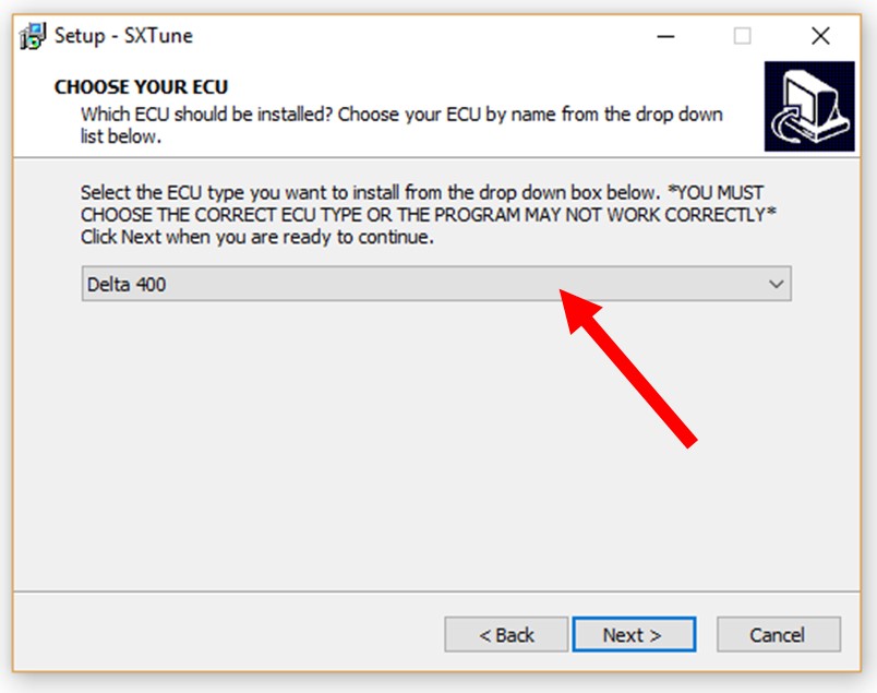
6. Click OK for the first window and in the second window choose your ECU from the drop-down list
7. Click through the rest of the dialogues in order to complete the installation..
Troubleshooting the Installation Process
Most installation problems are due to failure to update Windows to its latest version, not being logged in as administrator or already having a previous version of SXT started up and running whilst trying to install the latest version.
Connecting to ECU with SXTune
Basic Requirements
- Windows PC running Windows 7 or later.
- CAN programming interface.
- A DB9 connector on your engine loom (or less commonly a separate bench programming lead), or your car’s OBD port, to connect to the CAN interface.
- 12 volt permanent supply (Battery)
- Switched 12 volt supply (ignition switch)
- Latest copy of SXTune software installed.
Importance of Permanent and Properly Switched Supply on the AMPSEAL 35
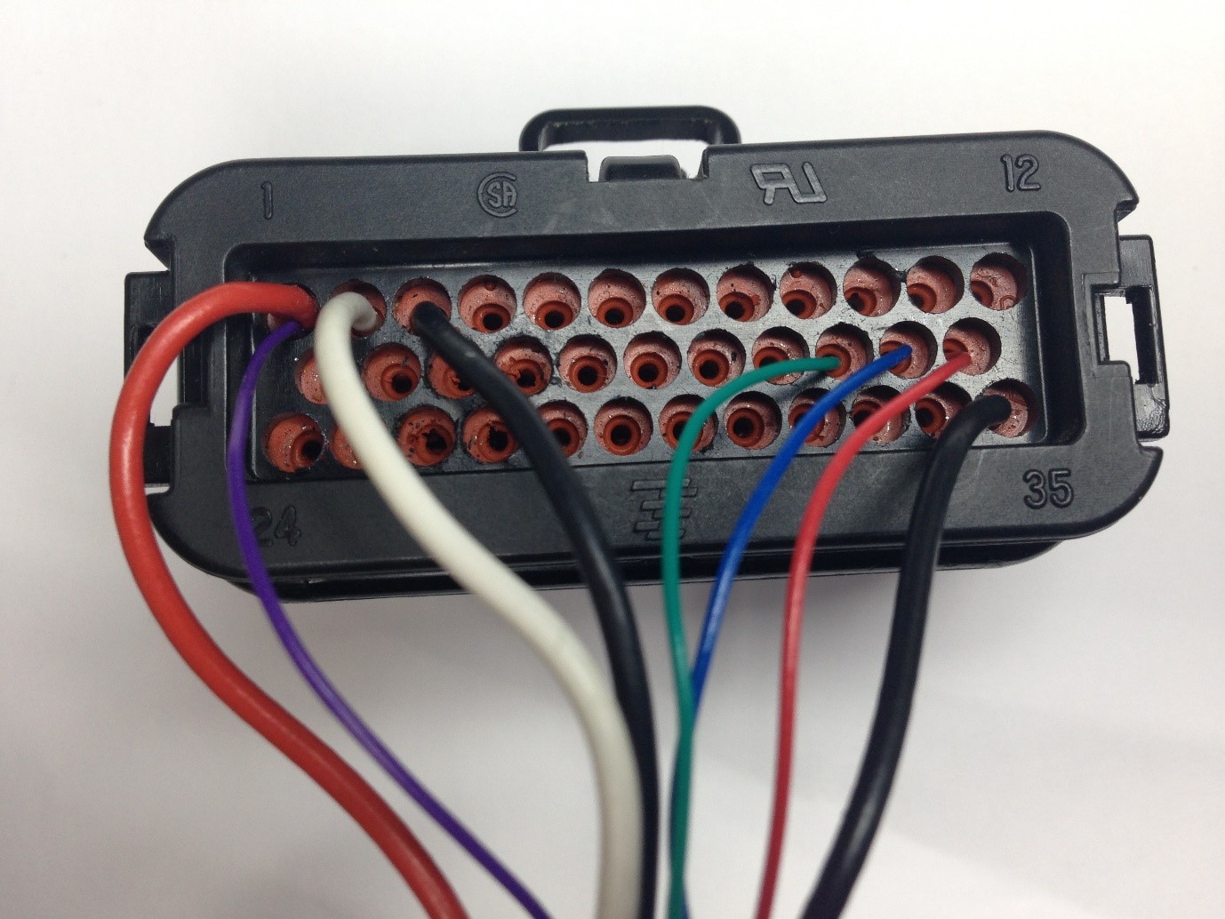
It is essential that the supply to pin 1 on the AMPSEAL 35 is a permanent supply, directly to (approximately) 12 volts, without passing through any type of switch. Pin 3 should also be a permananet quality connection to ground. It is also essential that the switched 12 volt supply on pin 2 is switched by a proper electrical switch (such as the vehicle's ignition switch) and not, for example, switched by touching a bare wire on to a battery terminal. A proper electrical switch allows the ECU to correctly debounce the signal when the switch is activated. Not having a good quality switch is likely to lead to erros when attempting to load firmware or a calibration file into the ECU.
Connecting the PC to the ECU
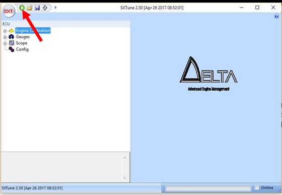
The supplied CAN interface is connected to the D-SUB 9 connector on your engine loom and to the PC via the supplied USB cable. In some cases the D-SUB9 connector will not be required and your connection will be made via your car’s OBD port. In this case you should have a lead with micro USB to OBD connectors which connects between the can interface and the OBD. Once the CAN interface has been plugged in to both the loom and the computer, you can connect to the ECU in SXTune by pressing the green connect button in SXTune.
Bench Programming Lead
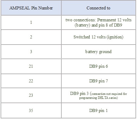
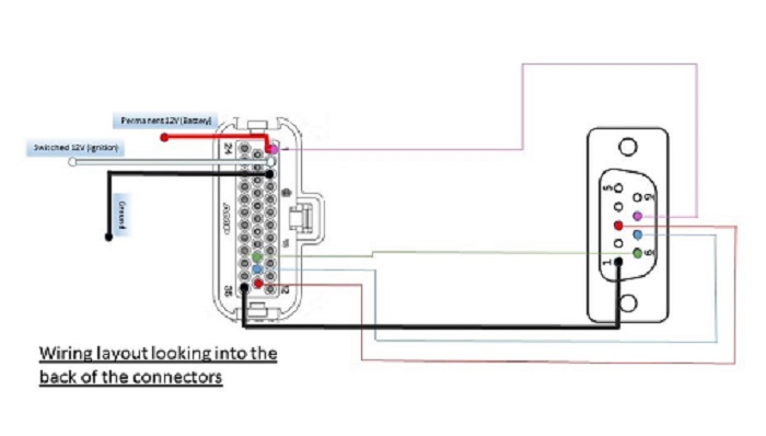
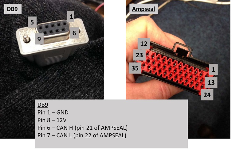
A dedicated programming lead incorporating a switch (to simulate the ignition switch) and a 12 volt mains adapter can be used, as supplied by SCS. Alternatively, the programming lead can be wired using the car’s 12-volt supply and 12-volt switched ignition. The required connections for the D-SUB 9 way female connector and the AMPSEAL 35 female connector (776164-1) are shown in the table and two images below. NOTE: If you connect to the ECU via your vehicle’s OBD port then the D-SUB connector will not be required.
Connection Problems
Description of the CAN interface LEDS
If SXTune does not connect to the ECU, some trouble shooting steps can regain communication. An understanding of the CAN interface's LEDs and CAN bus speed will be necessary. It is therefore useful to read and understand the information detailed below.
The CAN interface's bus speed is set in SXTune. It's important to recognise that this is the bus speed only of the interface and not the ECU. The speed of the interface's bus and the ECU's bus must be the same for communication to take place. We therefore set the CAN interface's bus speed to match the ECU bus speed. The CAN interface has two LEDs which indicate the status of communication between the interface and the ECU.
1. The green LED simply shows that the interface has power. It is important to realise that the CAN interface can be powered from both the engine loom and the PC. This means that in order to power down and reboot the CAN interface it is necessary to remove both cables from it.
2. The red LED flashes when it is connected to and communicating with the ECU. A flashing red LED shows that the CAN interface's bus is set to the same speed as the ECU's bus and the two are communicating with each other.
Given the above, the objective when troubleshooting should be to get the green LED continuously on and the red LED flashing to indicate correct comms between the ECU and the CAN interface (when the ECU and the ECU is switched on). This should then allow you to connect to the ECU with SXTune. If SXTune still does not connect to the ECU, even when the LEDs solid green and flashing red then, try removing your laptop's power cable (and use just battery), as this could possibly cause a ground offset which affects the CAN messages.
If the red LED is not flashing but either on continuously or off continuously, this indicates one of the following. Check them in the order below:
1.CAN interface has crashed and will need to be rebooted
2. CAN interface is not set to the same bus speed as the ECU it is connected to
3. ECU's firmware has become corrupted (possibly due to an unreliable power, ignition or earth connection during ECU programming) and its CAN bus is therefore not communicating
4. Wiring between the DB9 connector and the ECU has a problem.
5. ECU is not switched on properly (powered/grounded on pins 1, 2 and 3 of the 35 way black connector)
Trouble shooting
To check possibility 1, simply remove the cables from both sides of the CAN interface for 20 seconds. When the interface reboots it will remember what speed it was set to, so if the interface had been working before then it should begin flashing the red LED again. Plug the interface into the DB9 only, not the computer, and turn on the ignition. If you had problem 1 then it should now be fixed and the red LED will be flashing. Plug the the other cable into the computer and then connect with SXTune.
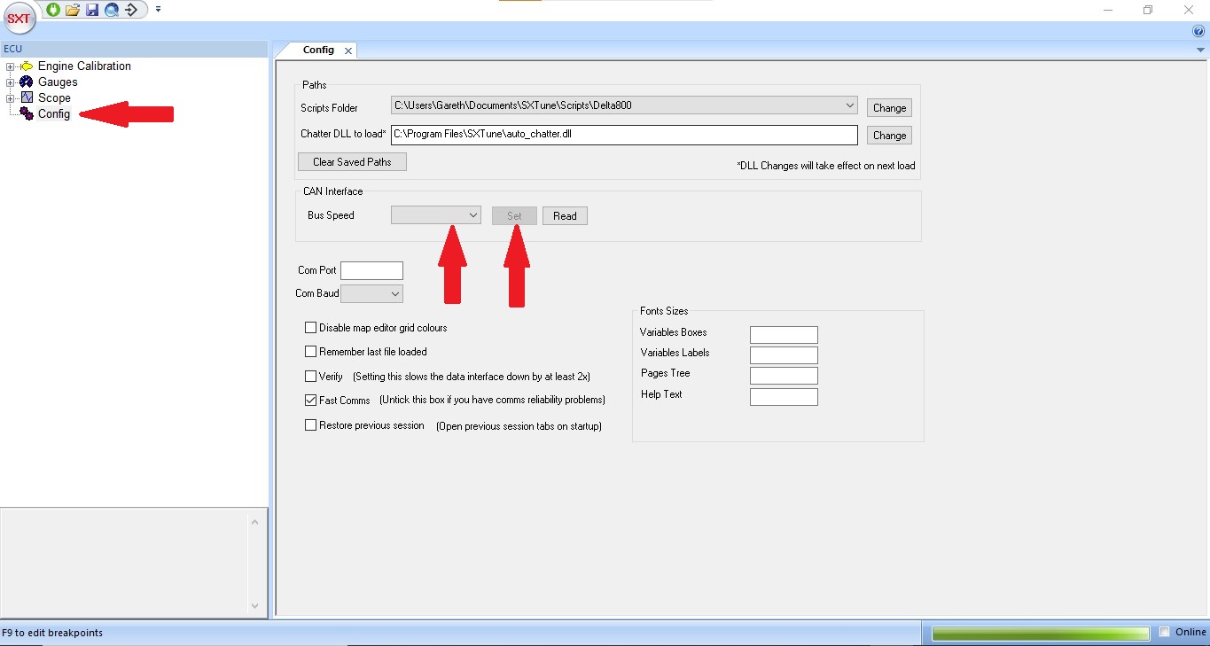
To check possibility 2, first reboot the CAN interface as detailed above, open SXTune and then plug in the interface. Go to config, the last option on the left hand menu, and choose 1Mbit/s in the CAN interface bus speed dropdown. Press set, to set the interface to this speed. You can check that the bus speed has been set properly, by choosing a different speed from the drop-down BUT NOT PRESSING set. If you now press read, then the speed you just set should be read back into the bus speed field. Unplug the cable from the computer and plug the other side of the interface into the engine loom's DB9 connector. With the ECU on and its bus speed set to the same speed you just set the CAN interface to, the red LED should now flash. If the red LED does not flash then try resetting the CAN interface bus speed to 500kb/s and 250kb/s. With the red light flashing you should now be able to plug in the computer cable and connect to the ECU with SXTune
To check possibility 3, first try to start the car. If the car starts then the firmware is fine. If however new firmware is required, it can be loaded as detailed in the section "Loading Firmware and Calibration". Set the CAN interface's CAN bus speed to 1Mb/s to start, then try 500kb/s.
To check possibility 4, you can do a continuity check between the DB9/DTM connector on the engine loom and the Ampseal 35 way black plug. The connections are shown in the image below.
To check possibility 5, ensure there is at least 12 volts on pins 1 and 2 and a good ground on pin 3 of the 35 way Ampseal connector