Configuring Input Sensors
This page describes how to use SXTune to configure the ECU for your input sensors.
PPS
Connecting the Pedal Position Sensor (PPS) to the ECU
Make sure that the Pedal Position Sensor (PPS) is correctly wired to the wiring harness you received (this maybe via some connections in connector B, via a separate 6 way connector for the PPS or directly to the AMPSEAL 35 way connector, depending on the particular engine you are working with.) Please check your pinout harness for more information. Do not connect the two signal wires from your PPS together, as they must arrive to the ECU as separate signals.
Connecting PC to ECU
Install SXTune and the CAN Interface and connect to the ECU as described in previous sections of this manual.
Callibration Procedure
The following procedure should be followed exactly in the order shown.
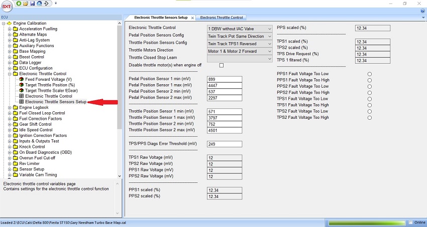
1. Make sure the ignition is still in the on position (but the vehicle is not running). Open the Engine Calibration menu, then the Electronic Throttle Control submenu and finally open the Electronic Throttle Control Variables pane.
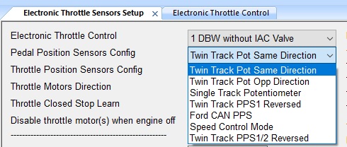
2. The two signals from the PPS can be observed in the PPS1 and PPS2 Raw Voltage (mV) field (they cannot be edited, only white fields may be edited). Firstly, check that both ‘PPS1 Raw Voltage’ and ‘PPS2 Raw Voltage’ start at a low value and increase when you press the pedal. If they do not, choose one of the options in Pedal Position Sensors Config until they both operate in the correct direction.
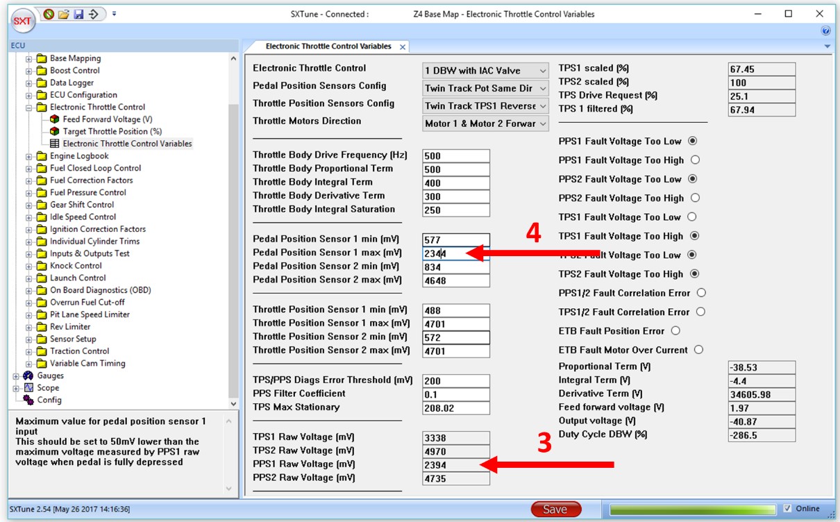
We will first calibrate the signal from the PPS1 sensor channel. Without touching the pedal, observe the voltage in the PPS1 Raw Voltage field (as indicated by arrow 1 in the image below). This value should be increased by 50 before being entered into the field Pedal Position Sensor 1 min (arrow 2). Increasing the value by 50 will allow a very small initial pedal travel before registering throttle demand.
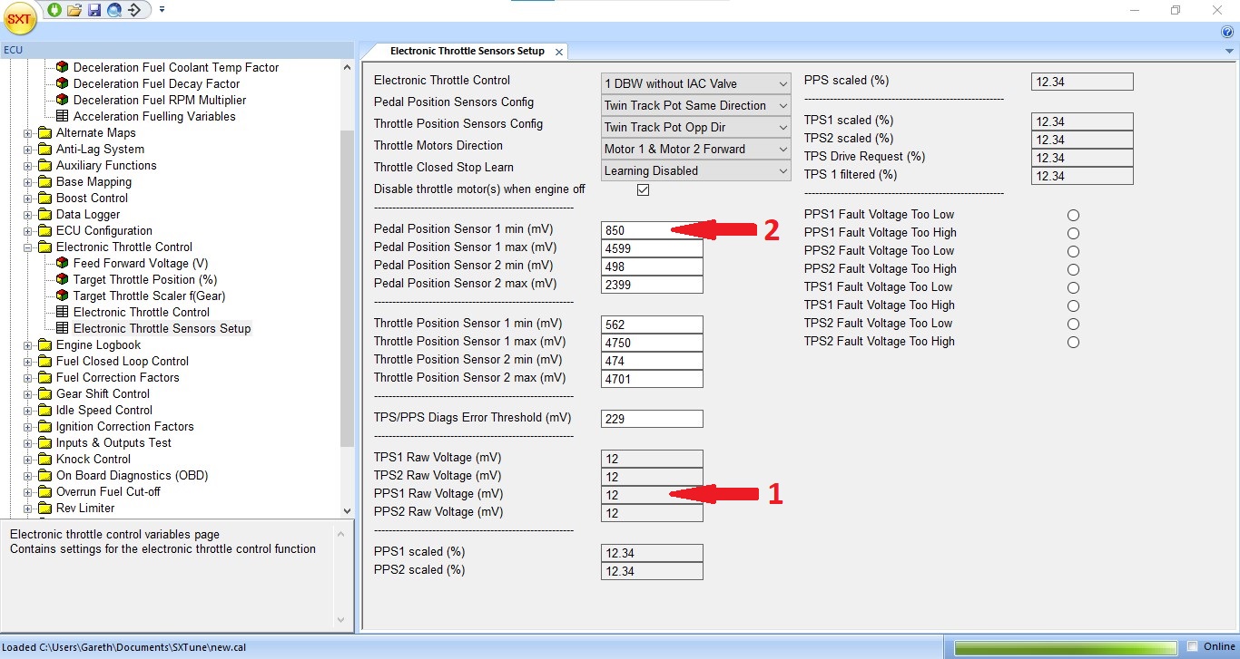
3. Now the throttle must be fully depressed. It is important to press the pedal as hard as possible (as you would in racing conditions) to ensure the pedal is pushed down as far as it will go. Observe the new value in the field PPS1 Raw Voltage (arrow 3). Subtract 50 from the value and enter the result into the Pedal Position Sensor 1 max field (arrow 4). Reducing the value by 50 will ensure that maximum throttle demand is detected just before the pedal is fully depressed.
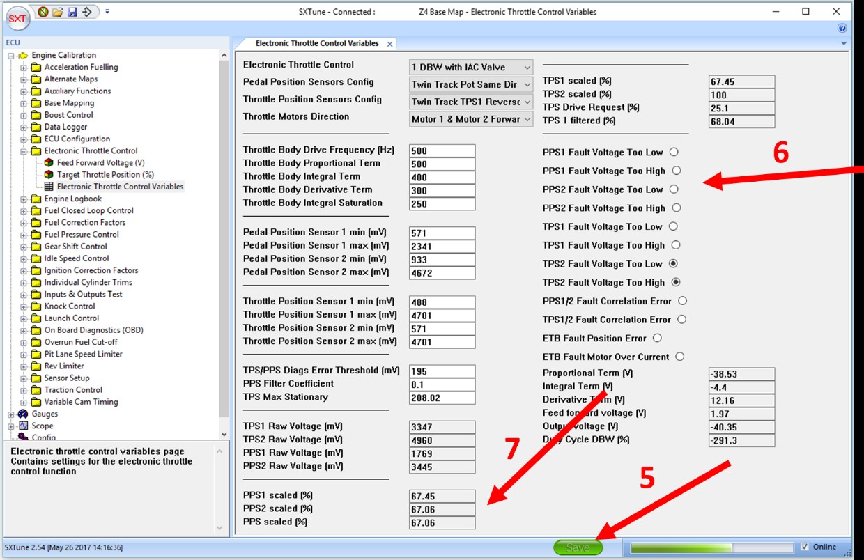
4. You should now follow the same procedure for both max and min values for the PPS2 sensor. Make sure you observe the value in PPS2 raw voltage (not PPS1 Raw Voltage) and fill in the value adding and subtracting 50 as before, but in the PPS2 fields. When complete, click Save to copy the values to the ECU (arrow 5). The save button should change colour from red to green. Turn the ignition switch off for 2 seconds and then turn it back on again. This will clear the stored faults (PPS voltages Too High/Low) which will have been logged as the PPS was being calibrated. The radio buttons should now be showing clear (arrow 6) where before some were set (you can see this in the diagrams above).
Check the Calibration
Operate the pedal over its full range and check that it changes from 0% to 100% for both PPS1, PPS2 and PPS (arrow 7) at the bottom of the SXT pane. The values may not be exactly the same but they should be quite close. Both must show 100% when the pedal is fully depressed and 0% when the pedal is not depressed. It should be possible to touch the pedal very lightly before pedal displacement is registered (this is due to the 50 mv added step 6). Similarly 100% throttle should be observed just slightly before the pedal is fully depressed.
TPS (Electronic Throttle)
Overview of Process
The electronically operated throttle body requires configuration with the butterfly valve exposed so that the valve can be changed from its resting position (limp home position set by a spring in cases where no IAC valve is used) to completely closed and then completely open. In these two states the voltage ranges produced by the body are read and entered into the ECU via SXTune. It is best to first have configured the PPS sensor as described above.
Configuring the TPS
Make sure the ignition is in the on position (but the vehicle is not running). Open SXTune and connect to the ECU.
Open the Engine Calibration menu, then the Electronic Throttle Control group and double click the Electronic Throttle Control Variables option.
1. First, temporarily set the Throttle Position Sensor 1 max(mv) value to 0 in order to generate a TPS fault. Click into any another box after entering the 0 (you will overwrite this value in step 5). Check that there is a TPS fault set in any one of the four TPS Fault Voltage Too High/Low indicators at the bottom right of the window. With a fault indicator set, the H-Bridge motor will no longer drive the valve (there should be no whirring sound from the throttle body anymore) and you will not risk trapping a finger when manually moving the butterfly during the rest of the setting up procedure.
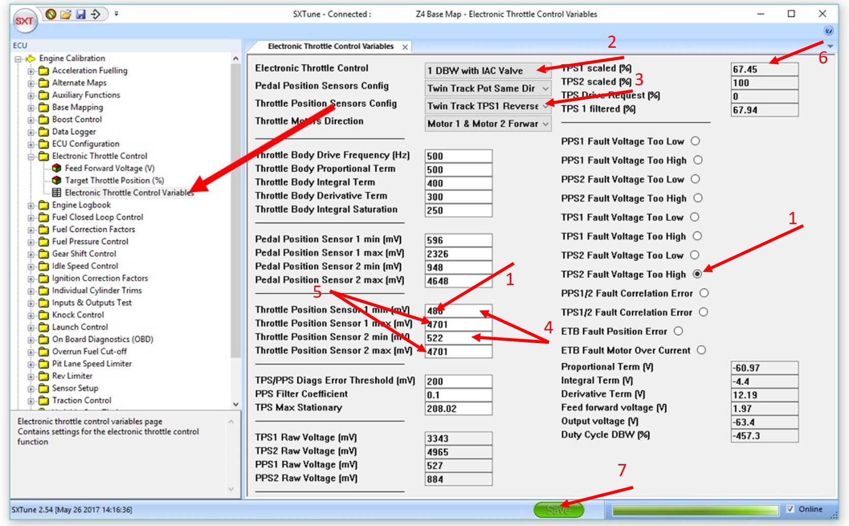
2. Configure the type of throttle body in Electronic Throttle Control. For example 1 DBW with IAC Valve would be chosen for a single throttle body with a seperate IAC Valve.
3. Choose the correct potentiometer directions in Throttle Position Sensors Config. This can be found by pushing the valve open and observing that the voltages in TPS1 Raw Voltage and TPS2 Raw Voltage both increase as the valve opens. If they don't, try the other options until they do.
4. Push the valve completely closed and note the TPS1 Raw Voltage and TPS2 Raw Voltage values. Enter these values into the Throttle Position Sensor 1 min(mv) and Throttle Position Sensor 2 min(mv) fields.
5. Now press the butterfly fully open, making sure it is at its maximum travel and cannot be opened any further. Again, note the TPS1 Raw Voltage and TPS2 Raw Voltage values. Enter these values into the Throttle Position Sensor 1 max(mv) and Throttle Position Sensor 2 max (mv) fields
6. Push the butterfly open and closed checking that the values in TPS1 scaled (%) and TPS2 scaled (%) move between to 0 and 100 and that the two values are with a few percent of each other as they change. Set the TPS/PPS Diags Error Threshold (mv) field to 249 if it is not already this value.
7. Press the save button at the bottom of the window, changing it from red to green. Turn off the ignition for a couple of seconds and turn it back on again. The TPS fault indicators should be clear. Operate the pedal and check the butterfly opens and closes without triggering any fault indicators.
TPS (Cable Throttle)
Overview of Process
The cable operated throttle body configuration is an iterative process where various maps are affected by throttle position and will therefore require calibration once the TPS values have been correctly matched to the throttle cable travel (whose process is described below).
Configuring the TPS
Make sure the ignition is in the on position (but the vehicle is not running). Open SXTune and connect to the ECU.
Open the Engine Calibration menu, then the Idle Speed Control group and double click the Idle Speed Control Variables option. In the first field, the Idle Control TPS/PPS Enable Limit (%), set this value to 0.
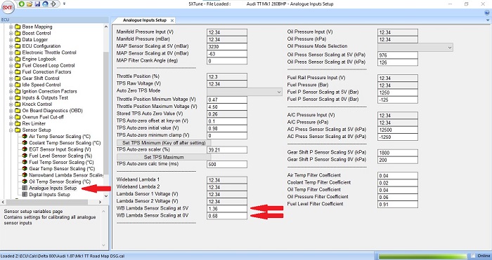
Open the Engine Calibration menu again, then the Sensor Setup group and finally open the Analogue Inputs Setup pane. Use the following procedure to configure the TPS.
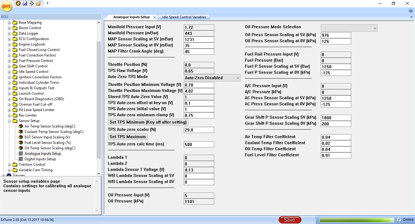
1. In the Auto Zero TPS mode dropdown, set the Auto Zero to disabled.
2. With the throttle closed, note the TPS Raw Voltage (V) voltage.
3. Enter this value into the Throttle Position Minimum Voltage (v) field (see figure above).
4. Now press the pedal (or twistgrip) fully open, making sure it is at its maximum travel and cannot be opened any further.
5. Note the TPS Raw Voltage (V) voltage.
6. Enter this value into the Throttle Position Maximum Voltage (v) field.
7. Operate the throttle over its full range, checking that the Throttle Position (%) changes linearly between 0% and 100% as the throttle pedal is operated from fully closed to fully open. Pay attention to the area around 0% and 100% throttle to check pedal position matches TPS% position. Check that the pedal stops actually do stop the pedal when the throttle body is completely open/closed (and on its throttle body stop) to prevent cable stretch (which will alter the configuration).
Analogue Wideband Lambda Sensor
General Information
Consider the best mounting point for the sensor. This usually means that it should be mounted with the sensor element facing down in order to avoid water vapour in the exhaust gasses entering into the metal shroud and damaging the sensor.
Whilst not essential, it is preferable to power the sensor’s heater from the ECU. This can be done by connecting pin A7 on the GDi4 to pin 4 on the Lamdba heater’s superseal connector (Consult SCS for other ECUs). This can help to protect the sensor by only switching its heater on when the car starts. If the heater is on and heats up before starting then cold water vapour may then hit the very hot sensor and crack it when the car starts. So having the car running before the heater fully heats the sensor is preferable.
Configuring the Sensor
Connect to the ECU. In ECU configuration and then outputs configuration, set the appropriate ECU pin (A7 on a GDi4) to lambda heater drive if you are using the ECU to drive the lambda heater (as advised in the previous section).
Go to Senor setup and then Analogue Inputs Setup. Input the scaling of the lambda sensor in the two WB lambda sensor scaling fields. Consult your sensor’s information sheet to find the lambda values corresponding to the sensor’s maximum and minimum voltage signals. Typical values are around lambda 1.36 at 5v and 0.68 lambda at 0v. Click the red save button at the bottom of the window to copy the values to the ECU.
Onboard Wideband Lambda Configuration
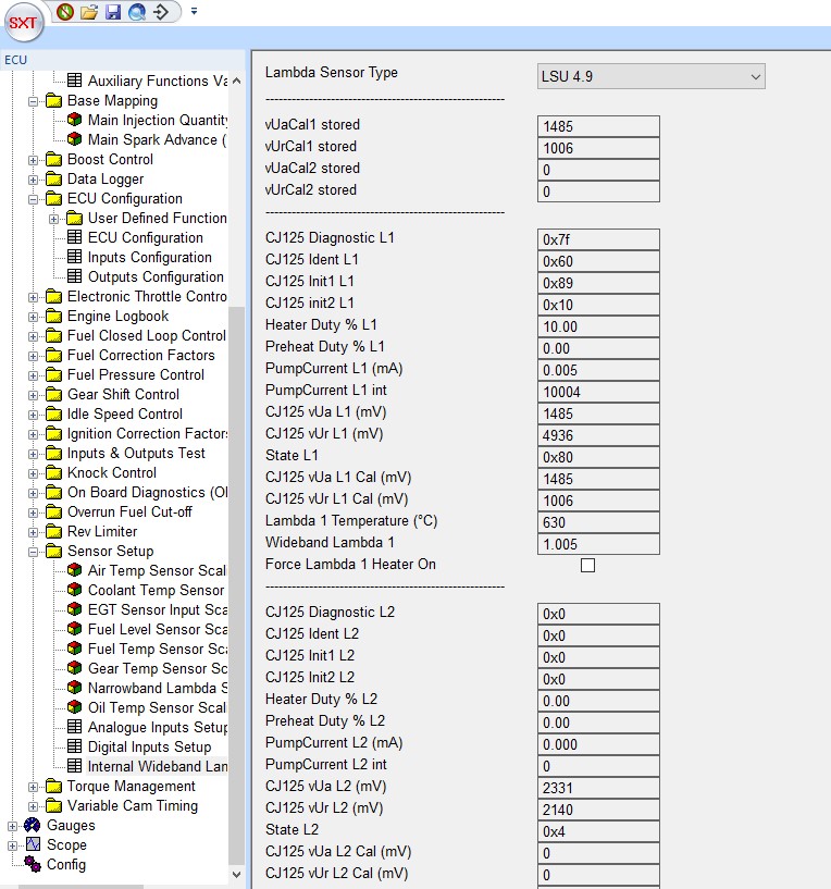
Select Sensor
To setup the wideband lambda hardware, choose the correct sensor type in the Lambda Sensor type drop down. The C125 Diagnostic L1/L2 will show 0xff if the sensors are connected and working correctly.
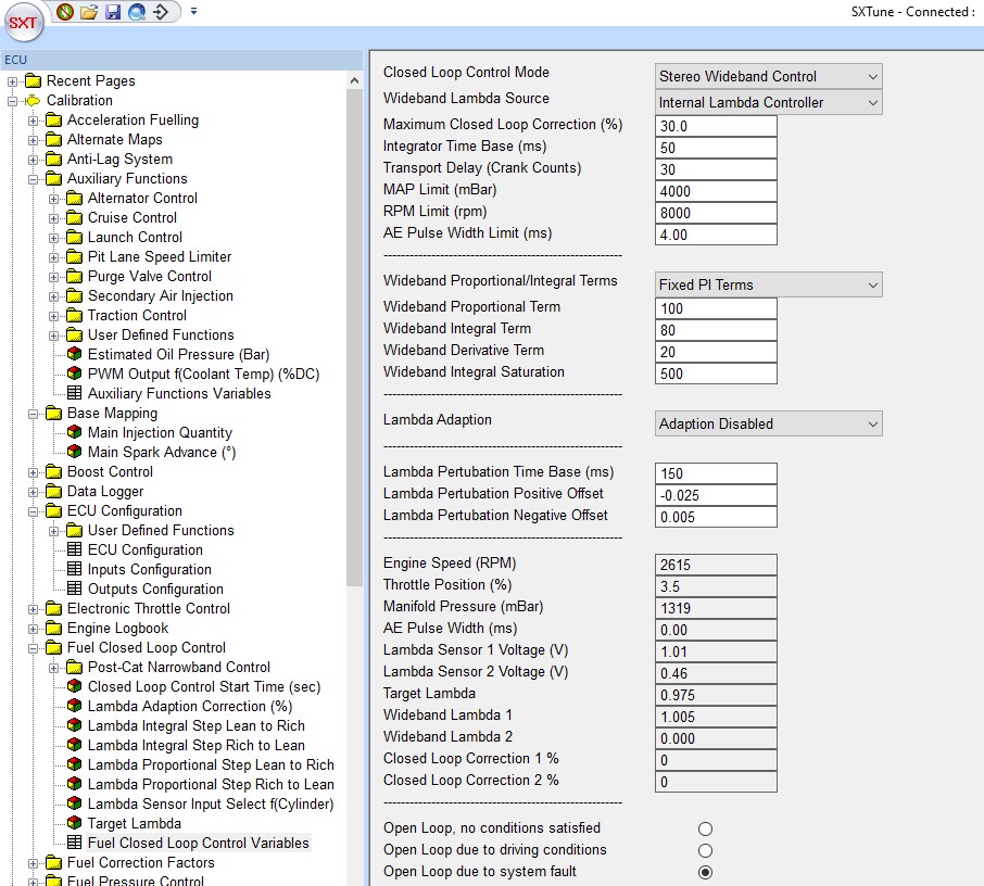
Closed Loop Settings
Choose Stereo Wideband Control for two wideband sensors, Single Wideband Control for one. The closed loop control settings should be set as shown below:
Flex Fuel Sensor 
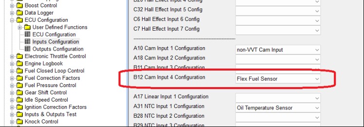
Initial Setup
You must first select the flex fuel sensor option as part of your input sensors configuration as shown below.
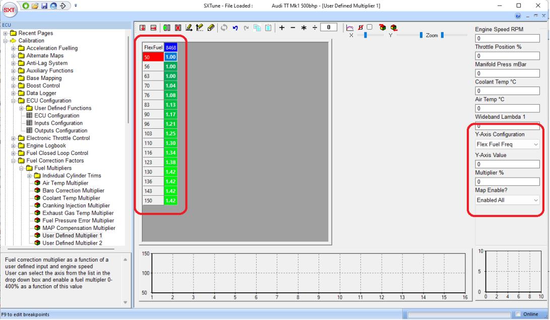
Fuel Correction Mulitplier
An example of a fuel correction table and the parameters requiring configuration are highlighted in the image below:
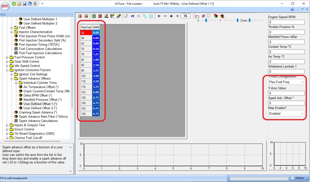
Spark Advance Offset
A spark advance offset of between -32 and +32 can be applied according to the map and variables as highlighted below: