SXTune Overview
This page describes some of the parameter groups found in the SXtune software and how ECU outputs (e.g. injection pulse width) are calculated from the parameters. Because the ECU is highly configurable, the customer is advised to familiarise themselves with parameters and how they combine to effect the outputs (e.g. injection pulse width, boost etc) they are interested in calibrating. There is also a description of some of the editing features.
Map Editor
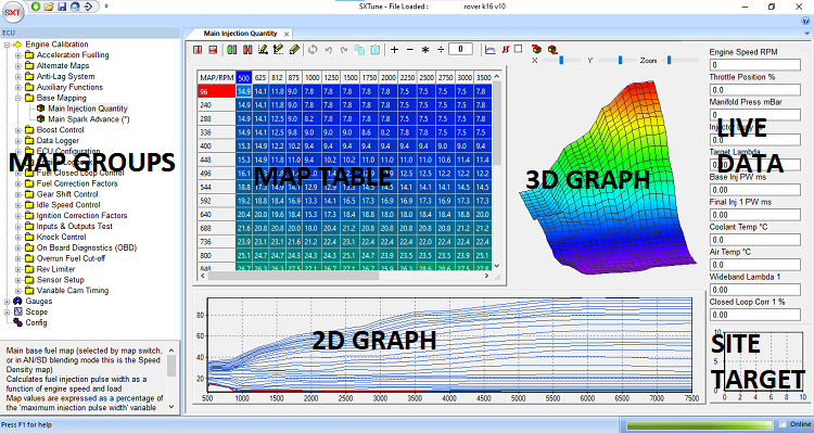
The Map Editor provides access to the maps used for calibration of the ECU. Specific maps are organised into groups selected by the right hand drop down and individual maps are accessed via the left hand drop down. A 3D graph of the map is shown to the right of the main map editor table and a 2D representation of rows/columns is shown under the main map editor table.
Map Editor ToolBar: The Map Editor Toolbar provides access to the cell operations listed below.
![]()
Interpolate Cells: The interpolate function automatically fills in cell values into the map in either rows or columns with linear interpolated values between the first and last cells.
![]()
Breakpoint Editing: Breakpoint editing mode for the X and Y axes is enabled by clicking the appropriate icon showing the axis to edit. To return to the main map editor click the breakpoint icon with no axes.
![]()
Insert/Delete Breakpoints: Inserting and deleting breakpoints is only enabled in breakpoint editing mode. To insert a new breakpoint select the point for insertion in the map and click the ‘Insert Breakpoint’ icon. The map will be fully recalculated to insert a new breakpoint with linear interpolated values in the new cells. To delete a breakpoint, select the breakpoint to be deleted and click the ‘Delete Breakpoint’ icon. By modifying breakpoints in this way, changes will not affect the existing calibration.
![]()
Undo and Reset: The last change made to a map can be undone by clicking the ‘Undo’ icon. The whole current map can be reset to the state at ECU power-up by clicking the ‘Reset’ icon.
![]()
Mathematic Operators: The maths operators – add, subtract, multiply and divide are available for the currently selected cell or group of cells. For example, to multiply the currently selected cells by 1.2 (increase by 20%), enter 1.2 into the maths box and click the ‘*’ icon.
![]()
Change 2D Plot Type: This icon changes the 2D plot through the following sequence: ‘Plot all rows’, ‘Plot current row only’, ‘Plot all columns’, ‘Plot current column’ allowing all aspects of the map to be viewed as a 2D slice.
![]()
Clear Bold Text in Cells: Cells that have been modified in the current map are highlighted in bold text. To clear all the bold text, click this icon.
![]()
Lock Trace Cell: To force the focus cell to be the current trace cell, tick this box. This avoids needing to press the space bar to make the focus cell jump to the current trace cell. This function will stop the user from selecting other cells or groups of cells for editing; only the current trace cell can be edited. To return to normal editing mode un-tick the ‘Lock Trace Cell’ box.
![]()
Keyboard Functions: Within the map editor tab changes are made either by typing a value into the load site or using PgUp and PgDwn keys to increase or decrease the values. Load sites are selected with the mouse, arrow keys (if the focus is set on the table) or by pressing the space bar which will select the current active load site.
A full break down of keyboard commands used in the Map Editor tab is provided below:
Function Keys:
- F1 – Help
- F2 – Move Forwards Between Maps within a Group i.e. between main fuel map and main ignition map
- F3 – Move Backwards Between Maps within a Group
- F5 – Refresh (reload) Current Map
- F8 – Edit Y Axis Break Points
- F9 – Edit X Axis Break Points
- F10 – Open File Menu
- F11 – Return to map editing from breakpoint editing
Shortcut Keys:
- CTRL + S – Save Current Map To File
- CTRL + L – Load Current Map From File
- CTRL + Q – “Quick Fuel” Function (See Quick Fuel Section Below)
- CTRL + PgUp – Coarse Adjust Value Up
- CTRL + PgDwn – Coarse Adjust Value Down
- SPACE – Jump to Current Trace Cell
Editing Keys:
- PgUp – Fine adjust value up
- PgDwn – Fine adjust value down
Quick Fuel:
Quick fuel is a method for rapidly setting fuelling whilst the engine is in steady state. Quick Fuel is only available if the ECU has a wideband Lambda Sensor connected, closed loop fuelling is turned on and the target lambda table is calibrated.
To use Quick Fuel hold the engine on a load site, ensure the target is as close to centre as possible. Wait until the closed loop compensation has stabilised at a value and press CTRL+Q. When CTRL+Q is pressed SXTune will adjust the current load site injector pulse width based on the current value + or – the amount of closed loop lambda adjustment. When Quick Fuel has been activated on a load site the closed loop fuel correction should now read zero.
Quick Fuel is intended as a tool to help rapid calibration of low load and engine speed load sites. Its use should be limited at high engine speeds and care should be taken when using Quick Fuel to validate that the entered value is sensible and correct. It is always recommended that a Dyno lambda sensor or similar is used as well as an on-vehicle lambda sensor to validate the on-car reading.
SXTune Parameter Groups
Acceleration Fuelling
Acceleration fuelling is calculated by measuring a change in throttle angle (delta TPS) and using this term multiplied by a global scaling factor and coolant temperature and engine speed compensations to generate an injection pulse width term that is added to the final injection pulse width. The diagram below shows the operation of the transient fuelling enrichment.

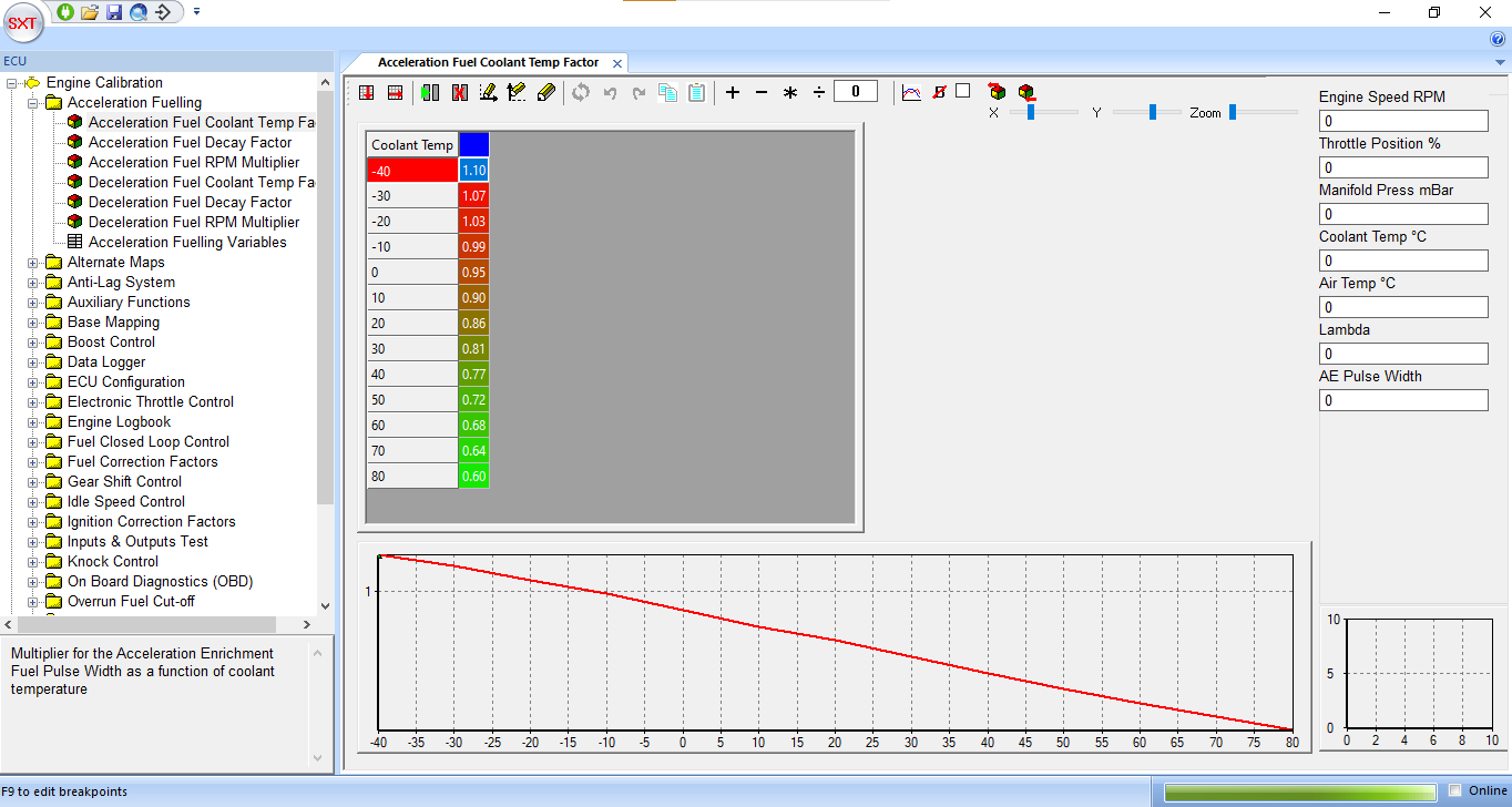
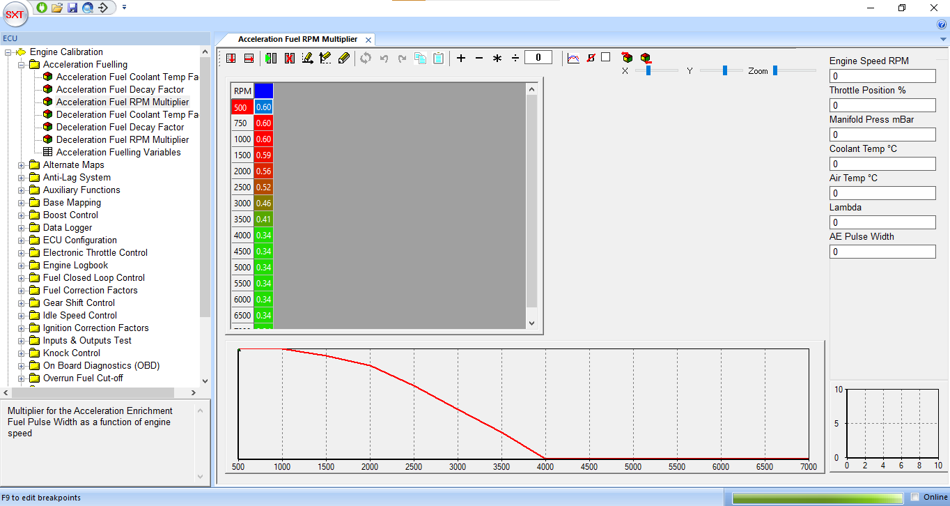
The acceleration fuelling value is multiplied by the ‘Acceleration Fuel Coolant Temp Factor’ map which is a function of coolant temperature as cold engines require more acceleration enrichment. The value is also multiplied by the ‘Acceleration Fuel RPM Multiplier’ map which allows the acceleration enrichment to be varied with engine speed, typically less enrichment is required at higher engine speeds.
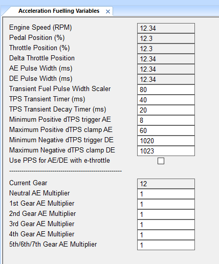
The acceleration fuelling variables page contains the variables listed below:
- Engine Speed - DE pulse Width -The first 6 are None user editable field showing current values
- Transient Fuel Pulse Width Scaler – the global scaler for acceleration fuelling
- TPS Transient Timer – Timer (in milliseconds) over which the delta TPS value is calculated (see strategy illustration)
- TPS Transient Decay Timer – Timer (in milliseconds) which determines rate of acceleration enrichment term decay
- Minimum positive dTPS trigger AE – The minimum limit to enable acceleration fuelling calculation
- Maximum positive dTPS clamp AE – The maximum saturation limit of the acceleration enrichment calculation
- Minimum Negative dTPS trigger AE – The minimum limit to enable deceleration fuelling calculation
- Maximum Negative dTPS clamp AE – The maximum saturation limit of the deceleration enleanment calculation
Base Mapping
The base mapping group contains the maps required for primary fuel and ignition control. These are the two maps that will be used primarily when mapping an engine on a dynamometer.

- The load axis of the fuel and ignition maps will be either throttle position (TPS) or manifold pressure (MAP) depending on the primary load selection in ECU Configuration.
- The load axis breakpoints can be edited by pressing F8 and the engine speed breakpoints can be edited by F9, to return to the map press F11.
- When the engine is running, the closest breakpoint to the current load and speed will be indicated by the ‘Trace Cell’ which is highlighted in black.
- The proximity to the nearest breakpoint is indicated by a visual representation, the ‘breakpoint proximity control’ in the bottom right hand corner.
- To edit the current trace cell, press the space bar and the ‘Focus Cell’ (the cell currently being edited) will jump to the trace cell.
- Values can be entered directly by typing in a number, incremented or decremented with Page Up and Page Down or a maths function can be applied using the maths toolbar at the top right hand corner.
- Cells that have been edited are highlighted with bold text which is cleared when either the map is changed or the clear bold text icon is clicked.
- To switch quickly between fuel and ignition maps using the keyboard, press F2 or F3.
Quick Fuel:
Quick fuel is a method for rapidly setting fuelling whilst the engine is in steady state. Quick Fuel is only available if the ECU has a wideband Lambda Sensor connected, closed loop fuelling is turned on and the target lambda table is calibrated. To use Quick Fuel hold the engine on a load site, ensure the target is as close to centre as possible. Wait until the closed loop compensation has stabilised at a value and press CTRL+Q. When CTRL+Q is pressed SXTune will adjust the current load site injector pulse width based on the current value + or – the amount of closed loop lambda adjustment. When Quick Fuel has been activated on a load site the closed loop fuel correction should now read zero. Quick Fuel is intended as a tool to help rapid calibration of low load and engine speed load sites. Its use should be limited at high engine speeds and care should be taken when using Quick Fuel to validate that the entered value is sensible and correct. It is always recommended that a Dyno lambda sensor or similar is used as well as an on-vehicle lambda sensor to validate the on-car reading.
Boost Control
Boost control is achieved by means of a bleed valve in the turbocharger wastegate controlled by a Pulse Width Modulated (PWM) signal from one of the ECU PWM outputs as selected in ECU configuration.
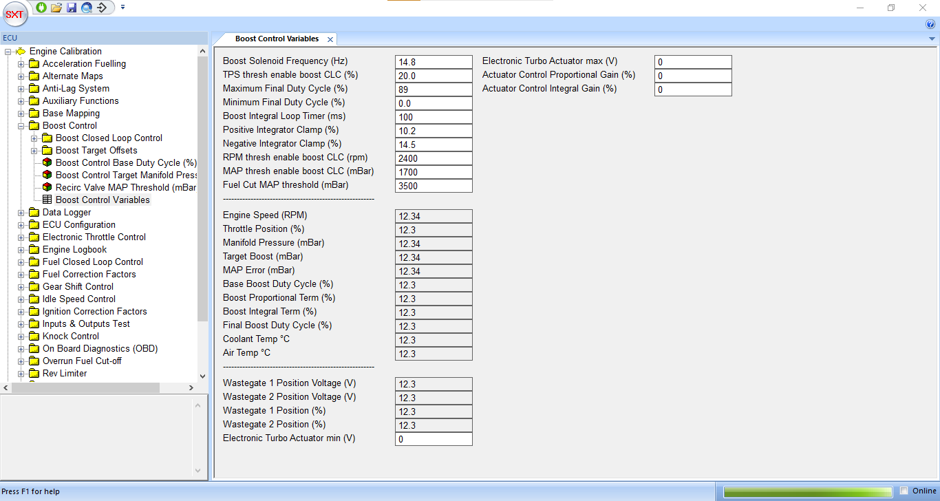
This Boost Control page displays values relating to the closed loop boost control strategy and is broken down into:
- Boost Solenoid Frequency – The piloting frequency at which the boost control solenoid will be driven in Hz.
- TPS Thresh enable boost CLC – the throttle position percentage above which the closed loop boost control strategy becomes active (set to 99.45 to disable closed loop boost control)
- Maximum Final Duty Cycle – The maximum boost control solenoid duty cycle percentage
- Minimum Final Duty Cycle – The minimum boost control solenoid duty cycle percentage
- Boost Integral Loop Timer (ms) – The time base for the boost PI controller integral term
- Positive Integrator Clamp (%) – The maximum positive value of the boost PI controller integral term
- Negative Integrator Clamp (%) – The maximum negative value of the boost PI controller integral term
- RPM Thresh enable boost CLC – the engine speed above which the closed loop boost control strategy becomes active.
- MAP thresh enable boost CLC – the MAP sensor value in mBar above which the closed loop boost control strategy becomes active.
- Fuel Cut MAP Threshold – the map sensor output in mBar at which fuel delivery will be completely turned off (for engine protection purposes).
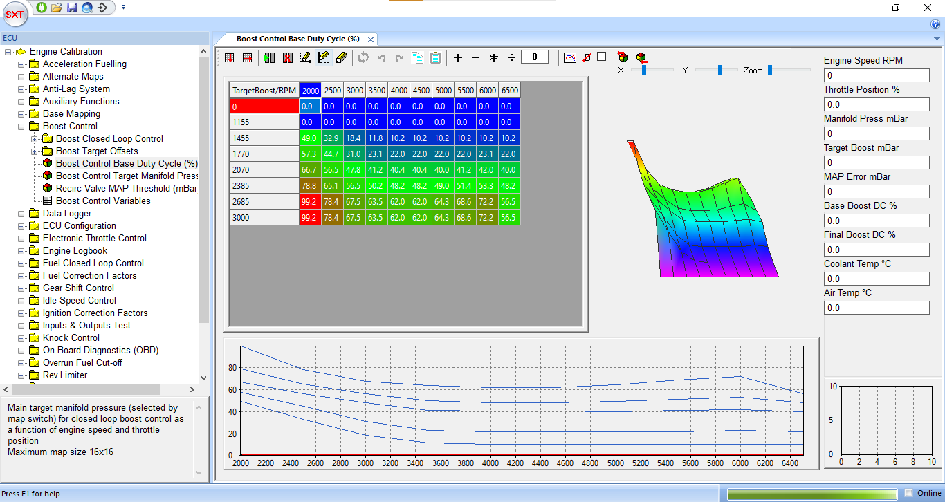
The open loop boost control term is calculated by a map as a function of throttle position and engine speed. This should be calibrated to achieve the target boost level before closed loop boost control is enabled. The target manifold pressure in mBar is calculated from a map also as a function of throttle position and speed.
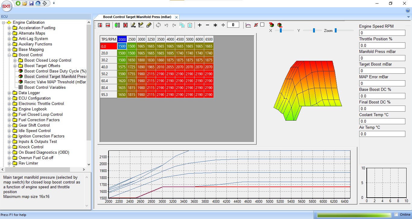
The open loop boost control term is calculated by a map as a function of throttle position and engine speed. This should be calibrated to achieve the target boost level before closed loop boost control is enabled. The target manifold pressure in mBar is calculated from a map also as a function of throttle position and speed.
Engine Logbook
The engine log book provides min/max and time spent at/above values for a variety of parameters. It also stores the 5 highest engine speeds attained to allow quick identification of engine over rev. It can be reset at any time by clicking the ‘Reset Logbook’ button.

Gauges
The gauges page shows live data in a graphical form for quick reference when setting up or calibrating an engine.
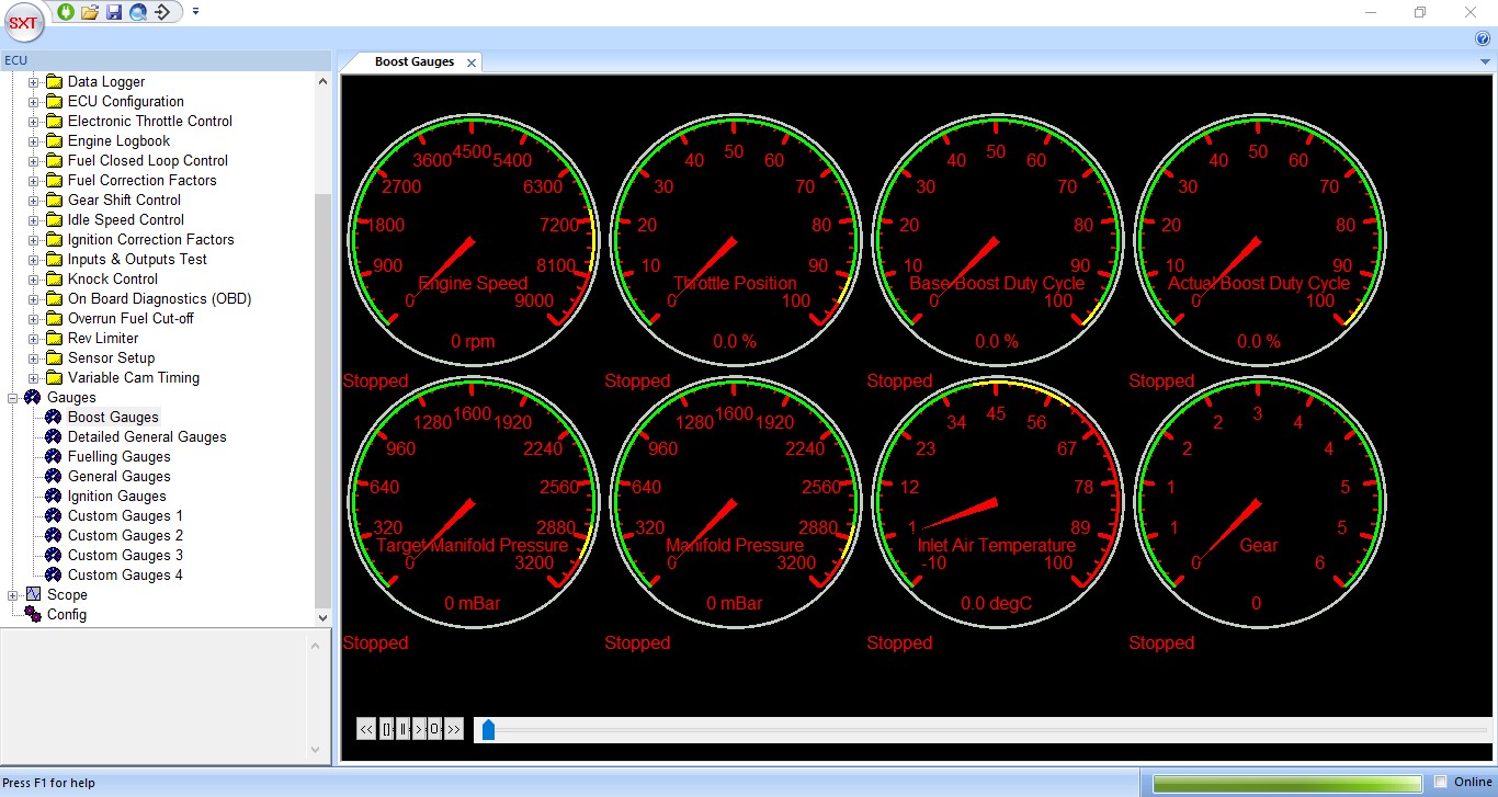
There are five preset gauge pages and four custom pages :
- - Boost
- - Detailed General
- - Fuelling
- - General
- - Ignition
- - Custom 1
- - Custom 2
- - Custom 3
- - Custom 4
Custom pages can be configured to show any gauges to group as required
Switching between gauges and text: Pressing the ‘Enter’ or ‘Return’ key when the gauges tab is active will toggle between large font text and graphical gauges.
Data Logging Function: The gauges page also provides a data logging function for recording, playing back or exporting as a .csv data shown on the gauges. This function is controlled via six buttons on the lower left of the screen which provide functionality for playback, recording, fast forwarding, rewinding, stopping and pausing the data logging. To export the data as a .CSV file (which can be imported directly into MS Excel) right click on a gauge and select the “Save Data To CSV” option or click ‘Record’ in the File Menu.
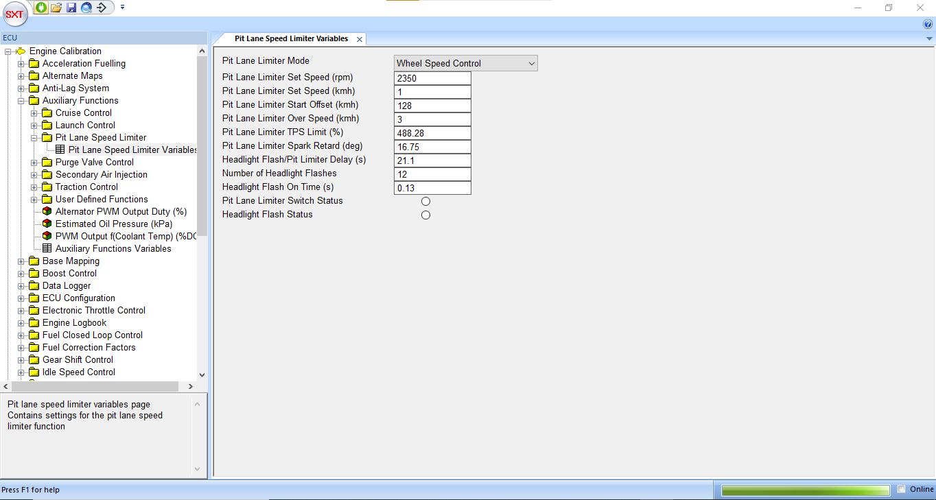
Pit Lane Speed Limiter
The Pit Lane Speed Limiter is used to control the maximum vehicle speed to a set value when the ECU pit lane speed limiter switch is enabled. The values required to calibrate the pit lane speed limiter function are in the ‘Pit Lane Speed Limiter’ variables page.
- Pit Lane Limiter Set Speed (kmh) – value in kmh of the desired pit lane speed limit.
- Pit Lane Limiter Over Speed (kmh) – value in kmh above which the pit lane speed limit will be disabled.
- Pit Lane Limiter Spark Retard (deg) – negative offset applied to the final spark advance value when the pit lane limiter is active. The value is ramped in automatically when the set speed is approached. This function is used to reduce the torque oscillations caused by the engagement of the limiter.
- Headlight Flash/Pit Limiter Delay (s) – The pit lane limiter switch can be used as a dual function ‘Flash to Pass’ and Pit lane speed limiter. A brief press of the button will invoke the headlight flasher function, while holding down the button for longer than this value will invoke the pit lane speed limiter.
- Number of headlight flashes – the number of flashes of the headlight flasher function.
- Headlight flash on time – the time period of the headlight flasher function.
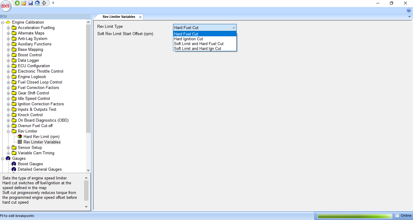
Rev Limiter
Rev limiting (over-speed protection) is implemented by a user selectable range of hard and soft cuts. The primary hard rev limit is set by a Map ‘Hard Rev Limit (rpm)’ under the Group ‘Auxiliary Functions’. This map is a function of coolant temperature, enabling a reduced rev limit to be set when the engine is too hot or too cold providing increased engine protection.
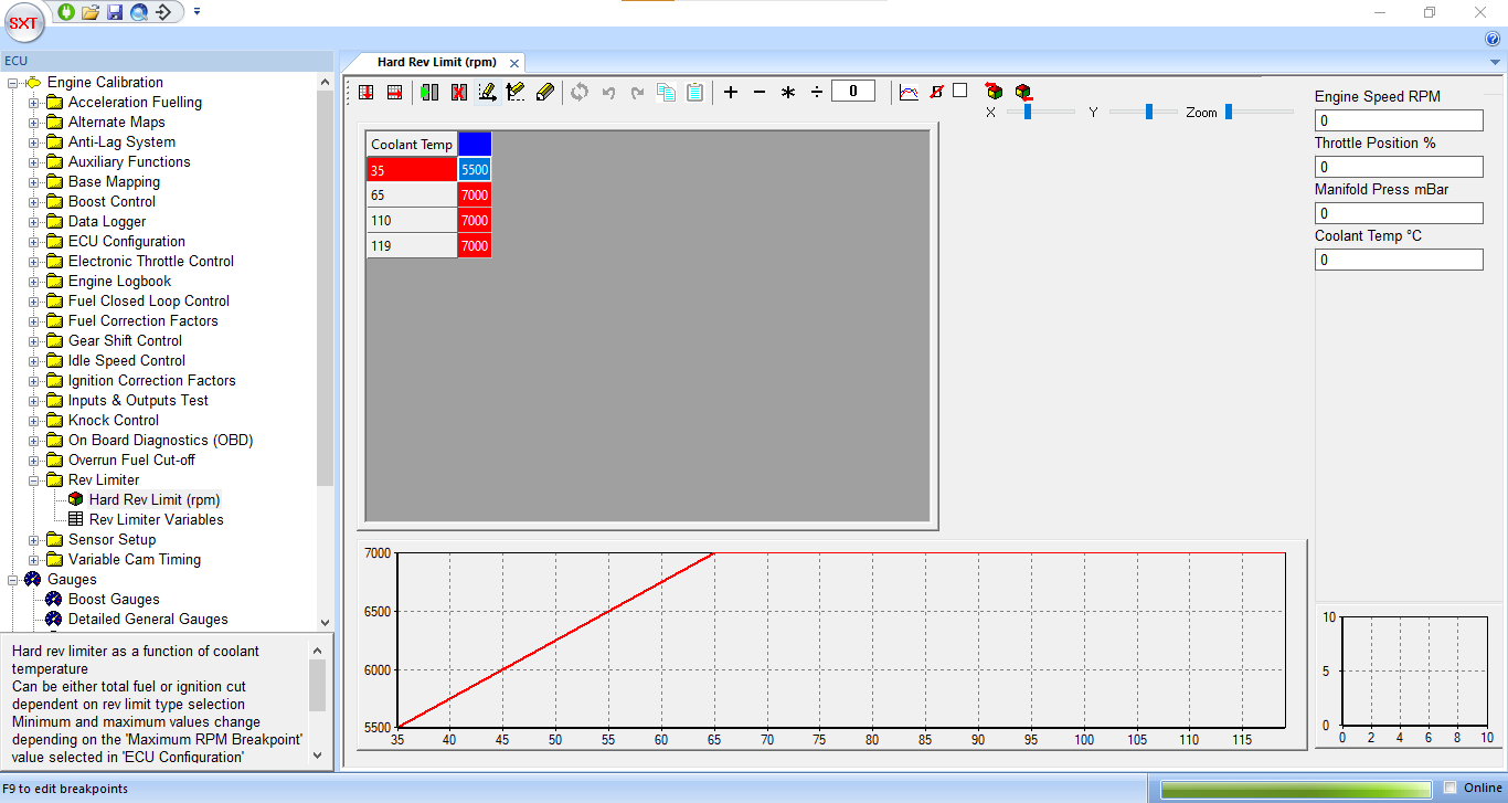
The rev limiter type is set by a drop-down box in the ‘Rev Limiter’ Variables page. There are options of hard fuel or ignition cuts, where either the fuel injection or ignition is completely switched off when the engine speeds exceeds the value obtained from the ‘Hard Rev Limit’ map. Also available is a soft limit which progressively reduces the engine torque as the hard limit is approached, giving a much smoother rev limiting effect. The start of the soft limiter is set by the value ‘Soft Rev Limit Start Offset (rpm)’ as an offset to the hard cut value. For example, if the hard cut is set to 8000rpm and the soft rev limit offset to 250rpm, the ECU will begin to reduce the engine torque at 7750rpm, increasing to a 50% reduction in torque at 7875rpm and culminating in a complete cut at 8000rpm.