Wiring
Find ECU Pinouts for:
Delta 400 Here.
Delta 700 Here.
Delta 900 Here.
Delta GDI6 Here.
Loom Connectors Here.
Delta 800 (Legacy) Here.
Delta 880 (Legacy) Here.
Delta GDI4 (Legacy) Here.
Delta Tornado (Legacy) Here.
Delta Typhoon (Legacy) Here.
Lambda
Analogue
These give a 0v to 5v output and are wired to pin A20 for lambda 1 and B24 for lambda 2
These are available with several different plugs to suit different applications.
Bare wire
Superseal
Inline
CAN
These comunicate with the ECU over the CAN bus and should be set to 500kbit/s
DTM
Inputs
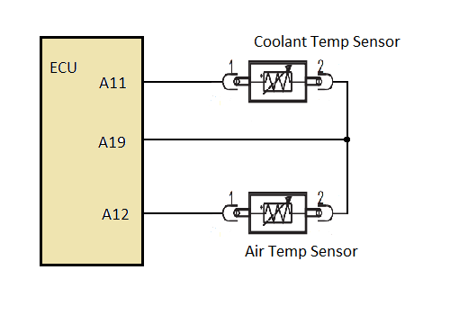
Temperature inputs are NTC and are referenced to Analog Ground.
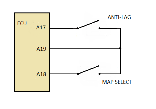
Auxiliary inputs (e.g. map switch,anti lag) are switched to Analog Ground (either A19 or A30).
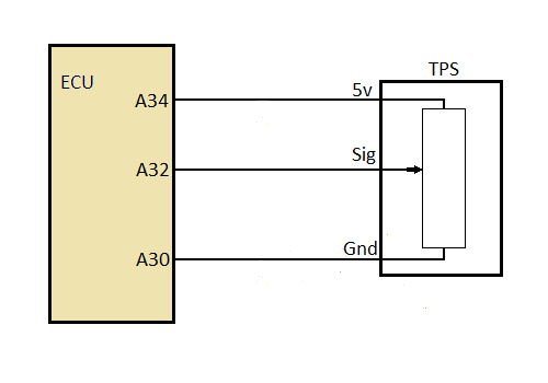
Linear inputs with a 0-5v (e.g. TPS, MAP,pressure sensors) will have a power, a ground and a signal wire.
Outputs
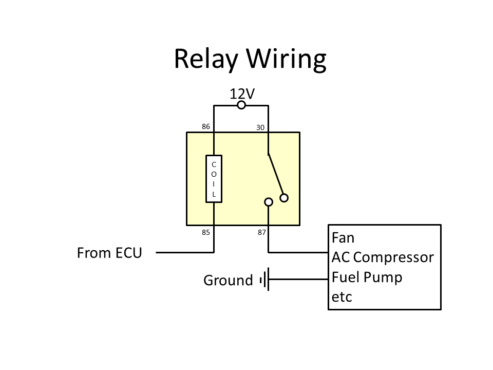
These are Low Side outputs so they controll the negative side of the device. A relay would be wired with a fused feed to the possitive (Pin 86) and the ecu to the negative side (Pin 85) as pictured