Troubleshooting Guides
This page covers the most common areas for trouble shooting in different applications.
Troubleshooting For Mini
Crank Sensor Issues
1. Sensor wiring polarity, are the signal and ground the correct way round. Commonly used Ford and Magneti Marelli sensors have opposite polarity but the same connector.
2. Sensor gap, must be between 0.5 and 1mm, perpendicular and central to the teeth on the trigger wheel.
3. ECU power supply, ensure that it remains on when cranking (e.g. NOT connected to accessory position on fuse box) and provides at least 10V on both pins 1 & 2 of the ECU when cranking.
4. Wiring routing, ensure that the crank sensor wiring does not go near the HT leads.
5. Cranking speed, minimum 150rpm.
6. In SXTune ECU Configuration, ignition output type selected as ‘Wasted Spark’ (or ‘Distributor for SPI engines) NOT ‘EDIS’!
7. In SXTune ECU Configuration – Inputs Configuration, is the correct trigger wheel type selected. Possible options are 36-1 for a trigger wheel on the damper pulley, SPI or K-series (for MPI) for a trigger wheel machined into the flywheel
8. In SXTune ECU Configuration – Inputs Configuration, is the correct ‘crank sensor input configuration’ selected? Possible options are VR (Variable Reluctance) or Hall Effect. 99.9% of Mini installations are VR. If you don’t know which one you have, choose VR
9. Are the crank sensor or the teeth on the trigger wheel damaged (check for bent teeth, machining burrs, incorrect number of teeth or positions)
10. Monitor in the ‘Digital Inputs Setup’ page of SXTune when cranking, that it is counting crank teeth and shows ‘Synchronised OK’, or ‘Checking Phase’ (both are possible and correct until the engine starts)
11. If the sensor gap and trigger wheel have been checked and engine runs but cuts out, particularly at idle, then try enabling the ‘Glitch Filter’ (Delta 400 only) in the ‘Digital Inputs Setup’ page:
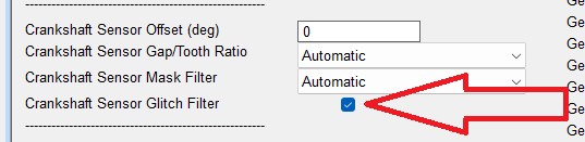
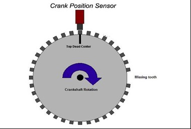
Correct location of 36-1 trigger wheel and crank position sensor
Injector and Ignition Testing
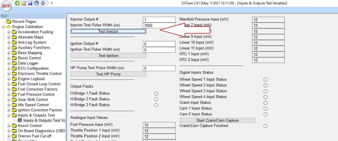
Test for an injector pulse using the injector output test function. Set the injector output to #1 and pulse to 3000us. You should hear the injector click when you press the ‘Test Injector’ button:.
And test for a spark using the ignition output test:
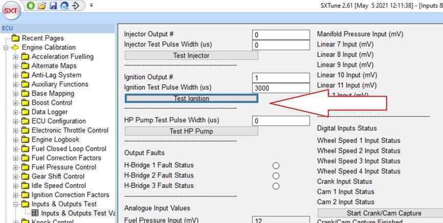
Fit a spark plug to an ignition coil and rest it on the cylinder head. Set the ignition output to #1 and pulse to 3000us. When you press the ‘Test Ignition’ button you should get a spark at the spark plug
Communications Issues
The first thing to check is that you have 5V at the green wire on the throttle position sensor with the ignition on. If you do, then the ECU is awake and communicating. If not then you may have a wiring fault in the power supply, make sure that you have 12V on pins 1 and 2 of the ECU and ground on 3. If that still doesn’t give 5V on the green wire then there is a hardware problem in the ECU and it should be returned to SCS Delta for test and repair or replace.
If there is 5V on the green wire then the next step is to check the wiring to the DB9 connector on the wiring harness:
ECU Pin 23 – DB9 Pin 3 (Typhoon/Storm only)
ECU Pin 22 – DB9 Pin 7
ECU Pin 21 – DB9 Pin 6
ECU Pin 3 – DB9 Pin 1
If those are correct then you should return the USB-CAN interface to Specialist Components for test and repair or replace.
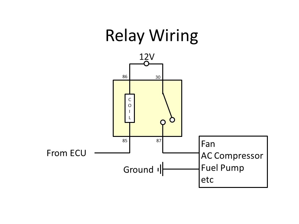
Relay Outputs and Cooling Fans
The ECU switches the ground side of relays. That means that there must be a 12V supply to both pins 30 and 86 of the relay. Relay pin 85 is switched to ground by the ECU, pin 87 is the switched 12V output to the load.
On most Mini wiring harnesses, pin A24 is connected to the cooling fan relay output. In SXTune, go to ‘ECU Configuration’ -> ‘Outputs Configuration’ and make sure that pin A24 is set to ‘Cooling Fan Relay 1 Output’. The coolant temperatures to activate the cooling fan are located in the ‘Auxiliary Functions Variables’ page where the current status of the cooling fan can also be seen.
Mapping Theory
In pulse width mode, the main fuel injection map is a table with 255 steps representing 0-100% of the maximum injection pulse width defined in 'ECU Configuration'. This means that each step in the map is 100/255 = ~0.4%. SXTune will automatically round any number manually entered to the nearest value defined by this resolution.
If each step of 0.4% is too large to control the AFR accurately on a given engine, then that means that the maximum injection pulse width number is too large. The correct value will be dependent on the flow rate of the injectors and the maximum power generated by the engine and the engine speed this occurs at.
For normally aspirated engines it should always be possible to choose a value for the max injection pulse width that gives sufficient precision at low loads and also allows the maximum power to be achieved without reaching 100% in the map. For supercharged or turbocharged engines, then it is recommended that MAP compensated primary load is selected to calculate larger pulse width values when under boost but retain required precision at low load. A MAP sensor is required for this calculation.
In volumetric efficiency mode, the steps are 0.5% VE and the fuel calculation is very different producing much higher precision, but requires a MAP sensor and flow rate data for the injectors. VE mode is not recommended for most A-series engines.